Cleanroom Filter Integrity, Qualification & Aerosol Test Systems
Complete measurement chains for installed HEPA and ULPA filter leakage testing, cleanroom qualification and laboratory filter evaluation. TOPAS aerosol generation, dilution and particle measurement are combined with Kanomax particle, airflow and pressure instruments around the applicable test method, facility layout and reporting scope.
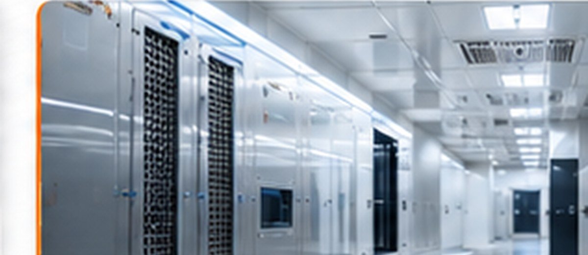
The complete installed filter system is tested—not only the filter media.
Installed-filter leakage testing verifies the assembled filtration system after installation. The test includes the filter media and the accessible interfaces through which unfiltered air could bypass the filter, including frames, seals, housings and supporting structures.
This is different from laboratory filter-element efficiency or factory scan testing. The installed test is configured around the cleanroom airflow system, filter location, available upstream access, downstream scan geometry, aerosol material, particle-counter range and the applicable acceptance procedure.
Cleanroom field qualification and laboratory filter testing require different system architectures.
Installed cleanroom qualification
Portable and field-configured equipment for installed-filter leakage scanning, airborne-particle classification, airflow verification, differential pressure, recovery testing and flow visualization.
Filter development and production testing
Controlled rigs for filter media and filter elements, including fractional efficiency, MPPS efficiency, scan leakage, pressure drop, dust loading, holding capacity and automated production checks.
Measurement coverage from installed-filter integrity to room performance.
Installed filter-system leakage test
Generate and verify the upstream aerosol, scan the downstream filter face and perimeter, locate local leakage and document corrective retesting.
Airborne-particle classification
Measure particle concentration at defined sampling locations and volumes for cleanroom or clean-zone classification using a suitable light-scattering airborne particle counter.
Air velocity and air volume
Measure terminal-filter velocity, unidirectional-flow velocity, supply and return volume, airflow balance and calculated air-change rate where required by the method.
Differential pressure and pressure cascade
Verify room-to-room, room-to-corridor and airlock pressure relationships together with direction, stability and alarm or monitoring behaviour.
Recovery-time measurement
Introduce a defined particle challenge and measure the decay to the specified cleanliness condition under the approved recovery-test procedure.
Flow visualization and protection assessment
Visualize airflow direction, recirculation, dead zones, door effects and interaction with equipment or operators in cleanrooms and separative devices.
Instruments selected for each stage of the cleanroom and filtration workflow.
TOPAS aerosol generation
Portable atomizer aerosol generators create repeatable liquid challenge aerosols for installed-filter integrity and recovery testing, with generator output matched to the room and air-handling system.
Confirm aerosol material, required output, compressed-air or integrated-compressor arrangement, introduction point, mixing and facility exhaust constraints.TOPAS aerosol dilution
Static or variable dilution systems reduce a high upstream challenge concentration to the usable range of the connected cleanroom particle counter.
Confirm dilution ratio, counter flow rate, concentration range, particle losses, stability and the intended upstream sampling arrangement.TOPAS upstream and downstream particle measurement
Cleanroom particle counters and scanning probes support upstream reference measurement and systematic downstream scanning of the installed filter system.
Confirm particle-size channels, counting efficiency, maximum concentration, sampling flow, probe geometry, scan accessibility and data recording.Kanomax cleanroom particle counters
Portable and handheld particle counters support cleanroom classification, verification, troubleshooting and location-based measurement workflows.
Confirm the required minimum particle size, flow rate, number of channels, sample volume, location map, audit trail and reporting format.Kanomax airflow and pressure instrumentation
Anemometers, airflow instruments and micromanometers support terminal-filter velocity, air volume, room differential pressure and HVAC performance checks.
Confirm velocity and pressure range, probe geometry, grid method, measurement uncertainty, temperature compensation and data interface.Filter performance testing beyond cleanroom field qualification.
General ventilation filters
Fractional efficiency and airflow resistance testing for general ventilation filter elements, with dust-loading and resistance-versus-captured-mass capability where required.
HEPA and ULPA filter elements
MPPS efficiency, integral efficiency and filter-element scan leakage testing using methods aligned to the applicable ISO 29463 or EN 1822 procedure.
Filter media and small elements
Characterize flat-sheet media, mini-elements, separators, cartridges and application-specific filtration components across defined aerosol, flow and pressure conditions.
Automated production quality control
Integrate fixtures, flow control, aerosol generation, upstream and downstream measurement, pass/fail logic, recipe control, traceability and report generation.
System configuration follows the applicable cleanroom or filter-test procedure.
ISO 14644-1
Classification of air cleanliness by airborne-particle concentration in cleanrooms, clean zones and applicable separative devices.
Defines the classification framework; sampling locations, volumes, particle sizes and room state must be established for the project.ISO 14644-2
Monitoring plans that provide evidence of cleanroom performance related to airborne-particle concentration.
Continuous or periodic monitoring does not replace the defined qualification tests; both are planned around facility risk and intended use.ISO 14644-3
Test methods for cleanrooms and associated controlled environments, including installed filter-system leakage and other performance tests.
The selected test, room condition, method, equipment and acceptance criteria must be documented before execution.ISO 29463 and EN 1822
Test and classification methods for high-efficiency filter media and filter elements, including efficiency at MPPS and scan-based leakage evaluation.
These standards address filter media and filter elements; they are not a substitute for installed cleanroom filter-system leakage testing.ISO 16890
Efficiency classification and test procedures for general ventilation filters based on particulate-matter efficiency, fractional efficiency and airflow resistance.
Applicable filter scope, face area, airflow and conditioning requirements must match the relevant part of the series.Information required to configure a technically valid test system.
Connected technologies for cleanroom qualification, aerosol generation and filtration testing.
Cleanroom filter integrity and qualification FAQ.
Is installed-filter integrity testing the same as filter efficiency testing?
No. Installed-filter integrity testing checks the complete installed system for local leakage through the media, frame, seal, housing and accessible bypass paths. Filter efficiency testing evaluates a filter element or medium under a controlled laboratory method.
Why is dilution used during an installed HEPA or ULPA filter leakage test?
The upstream challenge concentration can exceed the usable concentration range of a particle counter. A defined dilution system reduces the sampled concentration while preserving a known relationship to the upstream reference measurement.
Which parts of an installed filter system are scanned?
The accessible downstream filter face is scanned together with the perimeter, frame, gasket or gel seal, housing interfaces and other accessible locations where bypass leakage could occur.
Can one equipment set support other cleanroom qualification tests?
A configured equipment set can support installed-filter leakage testing, airborne-particle classification, airflow measurement, differential-pressure checks, recovery testing and flow visualization. The exact set depends on the cleanroom class, room geometry, airflow system and applicable method.