Remote I/O modules
DIN-rail analogue and digital modules bring distributed channels into Modbus RTU or Ethernet networks.
Convert field signals into reliable engineering data close to the process, with the isolation, scaling and communication needed by PLC, SCADA and cloud systems.
 Remote I/O
Signal conditioning
Energy data
Remote I/O
Signal conditioning
Energy data
Analogue, digital, pulse and utility signals
Isolate, scale, convert and timestamp
Engineering values and device status
PLC, SCADA, historian and cloud
The portfolio covers distributed I/O, signal isolation and conversion, temperature and process transmitters, energy measurement, wireless acquisition and configuration software.
DIN-rail analogue and digital modules bring distributed channels into Modbus RTU or Ethernet networks.
Convert, isolate and scale common industrial signals before they reach the control or acquisition system.
Interface thermocouples, RTDs and selected process variables to standard industrial outputs.
Acquire electrical or pulse-based information for asset, feeder and consumption monitoring.
Extend data acquisition to remote equipment where fixed network installation is impractical.
Configure ranges, scaling, communication and diagnostics with product-specific engineering tools.
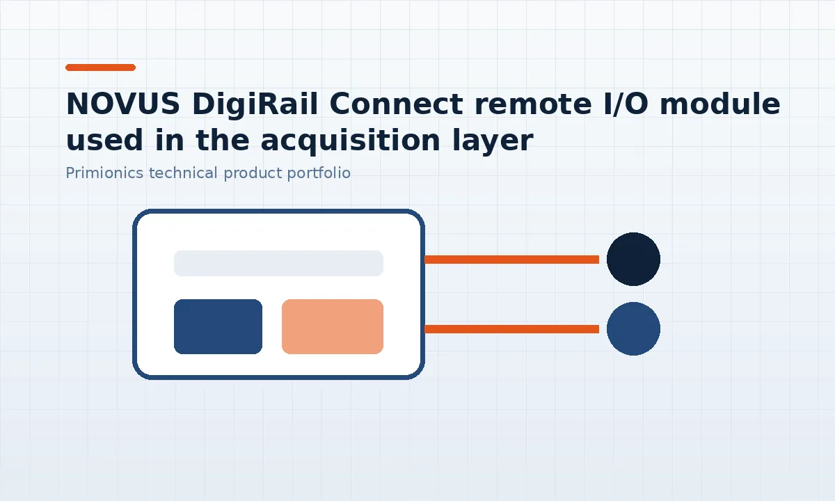
DigiRail Connect combines configurable analogue and digital channels with Modbus RTU over RS-485 and Modbus TCP over Ethernet. In the overall automation flow, it acquires, conditions field values and makes them available through Modbus RTU or Modbus TCP for PLCs, SCADA systems, gateways and monitoring platforms.
Select the acquisition layer from signal type, channel count, isolation, accuracy, location, communication and environmental requirements.
Add remote I/O and protocol conversion without replacing the existing PLC or field instruments.
Place channels near sensors to shorten analogue cable runs and simplify cabinet wiring.
Bring feeder, transformer, pulse and process-consumption data into the same monitoring environment.
Combine local acquisition with Wi-Fi or cellular connectivity for geographically distributed equipment.
Remote I/O modules collect analogue, digital and pulse signals near the process and expose them through a standard industrial network.
Acquire voltage, current, thermocouple or RTD signals according to module capability.
Read machine states, counters and pulse outputs from meters or equipment.
Use Modbus RTU or Modbus TCP to connect distributed channels to PLC, SCADA or gateway systems.
Check resolution, update rate, isolation, common-mode limits and fault behaviour for the actual signal source.
Signal conditioning protects the receiving system and presents the field measurement in a defined electrical range.
Break unwanted ground paths and limit the propagation of field-side faults where the selected conditioner provides galvanic isolation.
Translate between sensor inputs and standard voltage or current outputs used by the control system.
Convert non-linear sensor characteristics into engineering ranges when supported by the selected transmitter or conditioner.
Plan channel density, heat, terminal access and power distribution for DIN-rail installations.
Transmitters provide the first controlled conversion between the sensing element and the plant signal standard.
Connect thermocouples and RTDs through head, DIN-rail, duct or probe-mounted formats.
Measure environmental or process-air conditions with outputs selected for the monitoring system.
Use the appropriate transmitter range, wetted material and process connection for the medium.
Record input type, range, units and output scaling so maintenance can reproduce the setup.
Energy monitoring should connect electrical measurements with the equipment, production period or utility process that explains them.
Acquire voltage, current, power, energy or pulse outputs through suitable meters and interfaces.
Collect operating values from distributed electrical assets and forward them to a supervisory system.
Associate energy data with machine state, shift, batch or production output for meaningful comparison.
Define warning and alarm thresholds from equipment and utility requirements rather than from generic percentages.
Wireless links are useful where cabling is difficult, but radio coverage, buffering and recovery must be engineered explicitly.
Bridge selected RS-485 segments without changing the field-device protocol.
Connect supported loggers and gateways to local networks for configuration and data transfer.
Use 4G connectivity for remote sites with suitable VPN, access-control and data-volume policies.
Retain measurements locally where the device supports buffering during network interruption.
Product configuration tools reduce wiring and scaling errors when settings are managed as engineering data rather than left only on the installed device.
Select sensor type, engineering range and filtering for each channel.
Set address, baud rate, IP configuration and protocol role consistently across the network.
Use supported software to read configuration, inspect status and retrieve recorded data.
Store exported settings with panel drawings and commissioning documentation.
The acquisition layer can feed multiple consumers, but one system should remain authoritative for control and alarm actions.
Map remote channels into the control program with clear scaling and fault handling.
Expose measurements, quality and timestamps for supervisory display and historical analysis.
Publish selected data from supported IoT gateways without bypassing the plant security architecture.
Carry engineering units, equipment identity and alarm state into the monitoring layer.
Remote I/O and signal-conditioning systems require a signal list, network loading check, power and enclosure design, addressing plan and end-to-end loop verification.
Document input type, range, source impedance, isolation need and required update rate.
Check Modbus polling interval, device count, retries and expected data volume.
Size the DC supply, cabinet space and thermal margin for the installed modules.
Inject known values and confirm the displayed engineering result from field terminal to application.