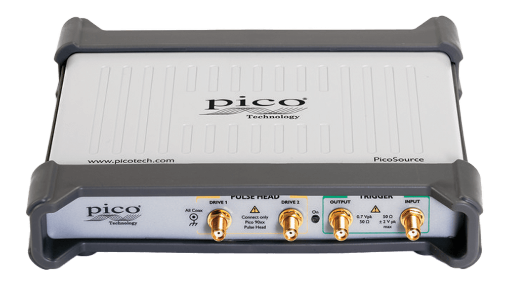
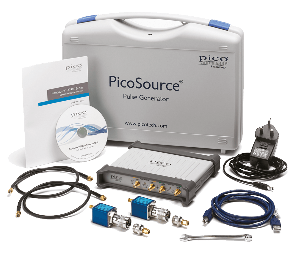
PicoSource PG900 Series — Differential Picosecond Pulse Generators
USB-controlled differential picosecond pulse generators for high-speed broadband measurement. Choose step-recovery diode outputs, tunnel-diode pulse heads, or a combined model for TDR/TDT, interconnect, semiconductor and timing work.
| Model | Output Type | Transition Time | Amplitude | Deskew |
|---|---|---|---|---|
| PG911 | Integrated step-recovery diode outputs | <60 ps | 2.5–6 V variable | ±1 ns, 1 ps steps |
| PG912 | External tunnel-diode pulse heads | <40 ps | >200 mV fixed | ±200 ps min., 1 ps steps |
| PG914 | Both SRD and tunnel-diode output sets | <60 ps / <40 ps | 2.5–6 V and >200 mV | SRD + tunnel-diode deskew |
Key Features
Step-recovery Diode Output Models
PG911 and PG914 provide integral 50 Ω SMA step-recovery diode outputs with adjustable 2.5 V to 6 V amplitude.
Tunnel-diode Pulse-head Models
PG912 and PG914 support external positive and negative tunnel-diode pulse heads with fixed 200 mV output and faster transition time.
Picosecond Timing Deskew
Differential deskew control in 1 ps steps supports precise timing alignment for differential interconnect and TDR/TDT setups.
Low-jitter Triggered Operation
Internal clock, external input and manual single-shot operation support lab and automated broadband test needs.
Broadband Measurement Stimulus
Fast transitions provide wide-spectrum stimulus for transmission path, device, network and port testing.
Compact USB Instrument
USB 2.0 PC connection, 5 V adapter power, compact dimensions and 5-year warranty support bench and rack use.
Specifications
| Parameter | Unit | Value / Description |
|---|---|---|
| MODELS | ||
| PG911 | — | Integrated step-recovery diode pulse outputs |
| PG912 | — | External tunnel-diode pulse heads |
| PG914 | — | Combined SRD outputs and tunnel-diode pulse-head support |
| SRD OUTPUTS | ||
| Output impedance | Ω | 50 |
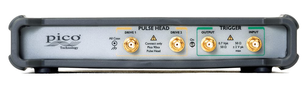
| Connector | — | SMA(f) |
| Amplitude | V | 2.5 to 6, adjustable |
| Transition time | ps | <60 ps smooth mode; <50 ps fast mode |
| Differential deskew | — | 2 ns range in 1 ps steps |
| TUNNEL-DIODE OUTPUTS | ||
| Output impedance | Ω | 50 ±2 |
| Connector | — | N(m) pulse heads |
| Amplitude | mV | 200 fixed |
| Transition time | ps | <40 ps |
| Deskew | — | 200 ps minimum / 300 ps typical range in 1 ps steps |
| TIMING / GENERAL | ||
| Pulse width | — | 200 ns to 4 µs in 25 ns steps |
| Jitter | ps RMS | 3.0 typical, 3.5 maximum relative to leading edge |
| Trigger input bandwidth | GHz | 1, DC-coupled |
| PC interface | — | USB 2.0 |
| Dimensions | mm | 190 W × 180 D × 40 H |
| Weight | g | 560 |
Applications
Impedance and Transmission
Launch fast differential pulses for impedance, reflection and transmission analysis.
Fast Pin Stimulus
Stimulate high-speed pins, packages and broadband devices with controlled fast edges.
Gigabit Link Characterization
Measure gigabit connectors, cables, backplanes and differential links.
Skew and Crosstalk
Use low-jitter fast transitions for timing, skew and crosstalk determinations.
Impulse-style Stimulus
Generate broadband impulse-like stimulus for radar and wideband network experiments.
Transmission Lines
Teach step response, transmission lines and high-speed measurement with a compact source.
Similar Products