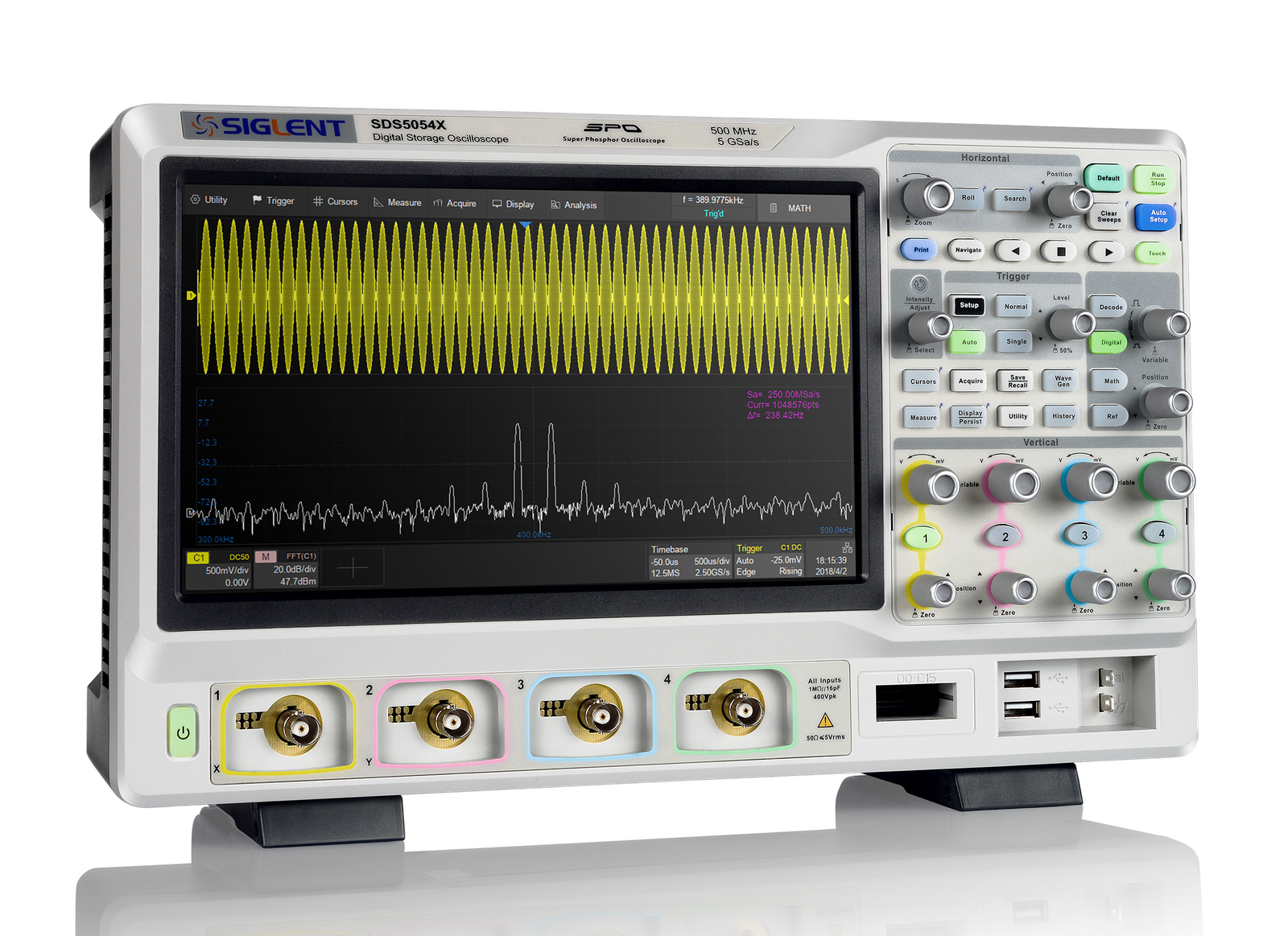
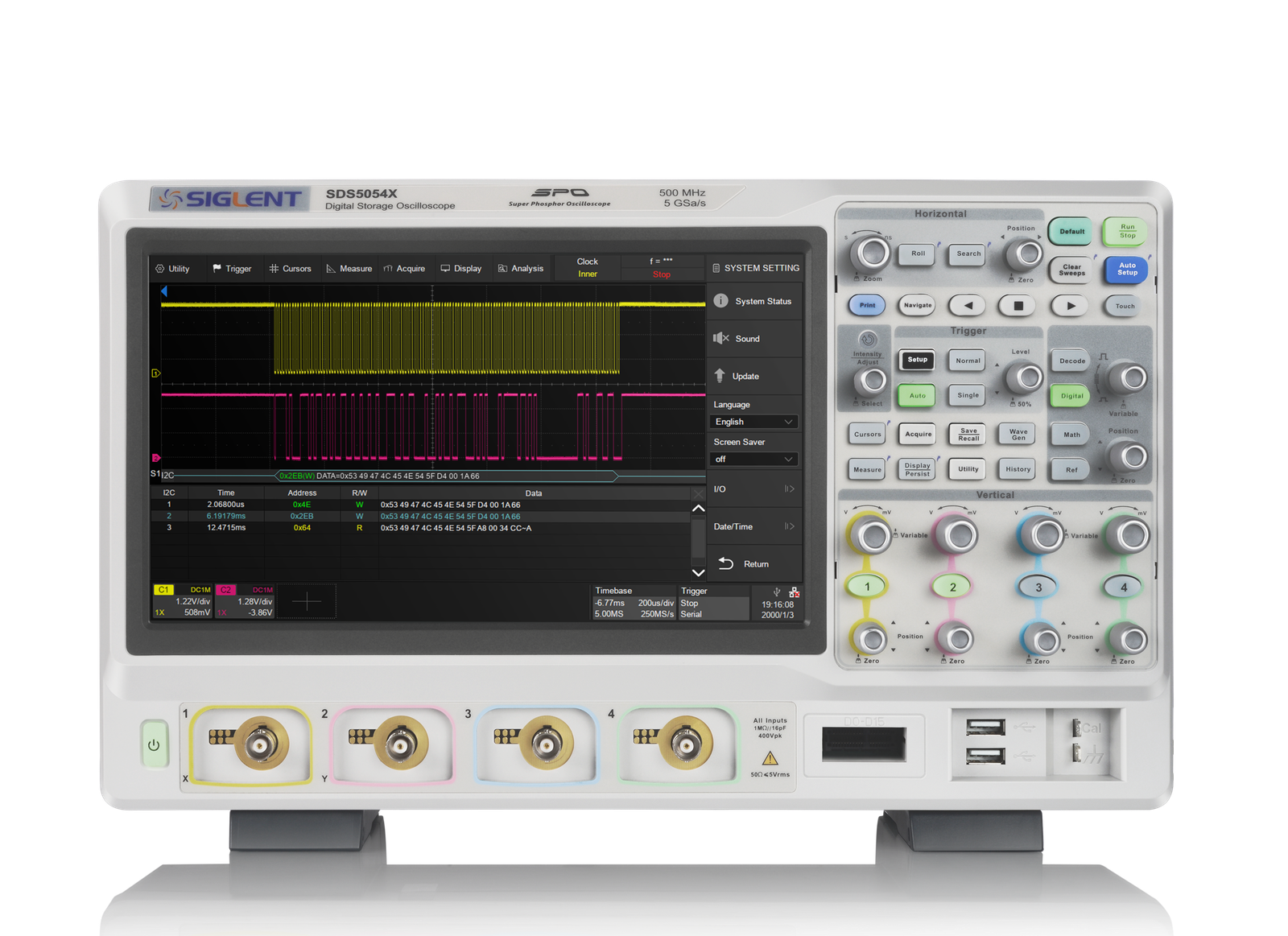

SDS5000X — 350 MHz to 1 GHz Super Phosphor Oscilloscopes
SIGLENT SDS5000X oscilloscopes cover 350 MHz, 500 MHz and 1 GHz bandwidths with 4 analog channels, optional 16-channel MSO, up to 5 GSa/s sample rate and up to 250 Mpts/ch record length. The platform adds SPO acquisition, serial trigger/decode, Bode plot, power analysis option, 25 MHz AWG option and 10.1-inch capacitive touch control.
| Model | Bandwidth | Channels | Sample Rate | Memory Depth | Capture Rate |
|---|---|---|---|---|---|
| SDS5034X | 350 MHz | 4 + EXT · 16 digital MSO option | Up to 5 GSa/s | Up to 250 Mpts/ch | 110k normal · 500k sequence |
| SDS5054X | 500 MHz | 4 + EXT · 16 digital MSO option | Up to 5 GSa/s | Up to 250 Mpts/ch | 110k normal · 500k sequence |
| SDS5104X | 1 GHz | 4 + EXT · 16 digital MSO option | Up to 5 GSa/s | Up to 250 Mpts/ch | 110k normal · 500k sequence |
Key Features
Up to 5 GSa/s · Up to 250 Mpts/ch
The SDS5000X captures fast embedded and power events with up to 5 GSa/s real-time sampling and up to 250 Mpts/ch record length.
SPO Capture and Sequence Mode
SPO technology provides up to 110,000 wfm/s in normal mode and up to 500,000 wfm/s in Sequence mode for intermittent-event capture.
4 Analog Channels + MSO Option
Current SDS5000X models provide 4 analog channels plus external trigger. The MSO option adds 16 digital channels for mixed-signal debugging.
Serial Trigger and Decode
Serial trigger/decode supports I²C, SPI, UART, CAN, LIN, CAN FD, FlexRay, I²S, MIL-STD-1553B, SENT and Manchester Code.
Bode Plot and Power Analysis
Bode plot supports loop-response checks with a USB AWG module or SIGLENT SDG generator. Power analysis is available as a configured option.
25 MHz AWG and Analysis Tools
The optional 25 MHz function/arbitrary waveform generator, 50+ measurements, histogram, trend, FFT, formula editor and search tools support lab debugging.
10.1-inch Touch Display
The 10.1-inch 1024 × 600 capacitive touch display supports multi-touch operation, mouse/keyboard control and common one-button shortcuts.
Remote Control and Automation
LAN, USB, web control and SCPI support integration with automated test workflows in lab, validation and production environments.
Specifications
| Parameter | Unit | Value / Description |
|---|---|---|
| VERTICAL | ||
| Bandwidth | MHz | 350 / 500 / 1,000 model-dependent |
| Analog channels | — | 4 + EXT trigger |
| Digital channels | — | 16 with MSO option |
| Vertical scale | V/div | 0.5 mV/div to 10 V/div |
| HORIZONTAL | ||
| Sample rate | GSa/s | Up to 5 real-time sampling |
| Record length | Mpts/ch | Up to 250 |
| Waveform capture rate | wfm/s | 110,000 normal mode · 500,000 Sequence mode |
| Sequence / History | frames | Up to 100,000 segments / frames |
| TRIGGER AND DECODE | ||
| Trigger types | — | Edge · Slope · Pulse · Window · Runt · Interval · Dropout · Pattern · Qualified · Video/HDTV · Zone · Serial bus |
| Serial decode | — | I²C · SPI · UART · CAN · LIN · CAN FD · FlexRay · I²S · MIL-STD-1553B · SENT · Manchester Code |
| ANALYSIS / OPTIONS | ||
| Measurements | — | 50+ parameters · statistics · histogram · trend · gated measurement |
| Math | — | FFT up to 2 Mpts · arithmetic · integration · differentiation · square root · formula editor |
| Bode plot | — | Supported using USB AWG module or external SIGLENT SDG generator |
| Power analysis | — | Configured option for switching power measurements |
| AWG | MHz | 25 MHz function / arbitrary waveform generator option |
| MSO | channels | 16 digital channels · up to 1.25 GSa/s · up to 62.5 Mpts |
| DISPLAY | ||
| Screen | — | 10.1-inch capacitive touch · 1024 × 600 |
| Display modes | — | 256-level intensity grading · color temperature |
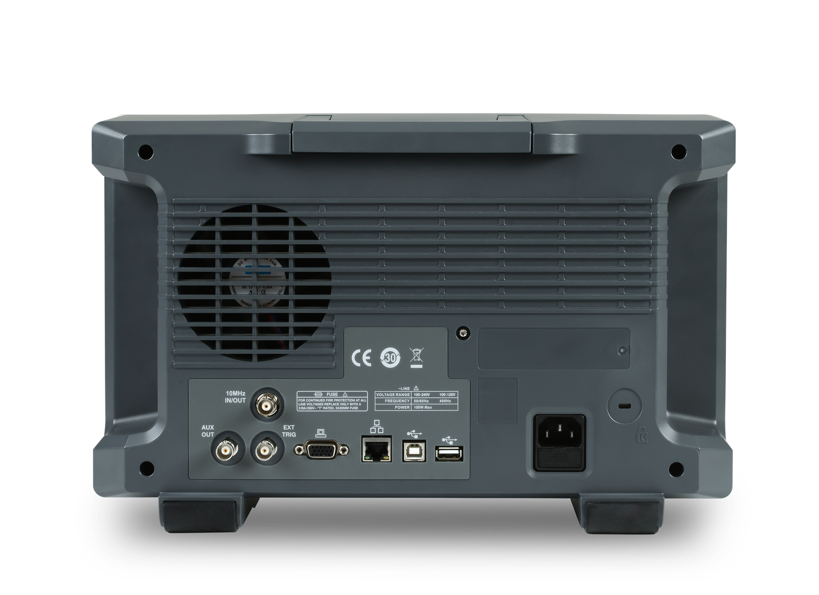
| CONNECTIVITY | ||
| Interfaces | — | USB Host · USB Device/USBTMC · LAN/VXI-11/Telnet/Socket/Web · Pass/Fail · Trigger Out · 10 MHz In/Out · VGA |
| Remote control | — | Built-in web server · SCPI · external mouse and keyboard support |
Applications
Embedded System Debug
Serial trigger/decode, long memory and mixed-signal option support firmware-hardware correlation across common digital buses.
Power Stage Validation
Bode plot and power-analysis option support loop response, ripple, switching behaviour and converter validation.
CAN / LIN / CAN FD Development
CAN, LIN, CAN FD, FlexRay, SENT and Manchester decode support ECU and vehicle-network debugging.
Automated Waveform QA
Mask testing, pass/fail output, SCPI and LAN control make the series usable in production and validation test frameworks.
PCB Signal Quality Debug
350 MHz to 1 GHz bandwidth and deep memory support edge-quality, ringing, timing and intermittent signal analysis.
Advanced University Lab
A practical 4-channel platform for embedded systems, power electronics, signal analysis and measurement training labs.
Similar Products